Background
10.1
This section of the EIA presents a summary of the analysis and findings
of the Quantitative Risk Assessment (QRA) study undertaken for the proposed
West Island Line (WIL) project. This project consists of approximately 3.3 km extension to the Island Line (ISL)
from the existing Sheung Wan Station (SHW) to the new Kennedy Town Station
(KET). The extension incorporates two new intermediate stations at Sai Yin Pun
(SYP) and Hong Kong University (UNV). Construction is scheduled to commence in early
2009 for completion in 2014.
10.2
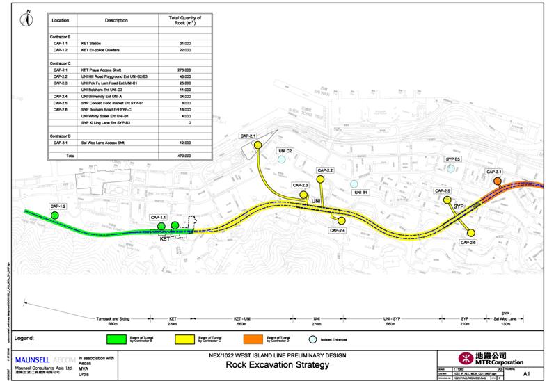
A significant length of the WIL tunnels, adits and station boxes will be
excavated in rock. The rock spoil is to be removed from a number of access
shafts and tunnels as shown in Figure 3. A significant amount of explosives
will be required for the construction of rock caverns, tunnels and adits for
the WIL. Therefore, the project allows for the construction and operation of an
underground explosives storage magazine located beneath Mount Davies.
10.3
Further details of the analysis pertaining to the storage, transport and
use of explosives for the WIL project are presented in the Appendix 10.
Legislation requirement and evaluation criteria
10.4
The
key legislation and guidelines that are
considered relevant to the development of the proposed West Island Line project
are as follows:-
·
Dangerous
Goods Ordinance, Chapter 295;
·
Environmental
Impact Assessment Ordinance (EIAO), Chapter 499; and
·
The
EIA Study Brief, Section 3.4.6
EIAO
Technical Memorandum (EIAO-TM)
10.5
The
requirement for a QRA of projects that involve the storage, use and transport
of dangerous goods where a risk to life is a key issue with respect to the Hong Kong Government
Risk Guidelines (HKRG) is specified in Section 12 of the Environmental Impact
Assessment Ordinance Technical Memorandum (EIAO-TM).
10.6
The relevant authority for a QRA study relating to an explosives
magazine storage facility, the transport and subsequent use of the explosives
is the Environmental Protection Department (EPD), as specified in Annex 22 of
the EIAO-TM.
10.7
Annex 4 of the EIAO-TM specifies the Individual and Societal Risk
Guidelines.
Hong Kong Government Risk Guidelines
(HKRG), EIAO TM Annex 4
10.8
Individual risk is the predicted increase in the chance of fatality per
year to an individual due to a potential hazard. The individual risk guidelines
require that the maximum level of individual risk should not exceed 1 in 100,000 per year i.e. 1 x10⁻⁵
per year.
10.9
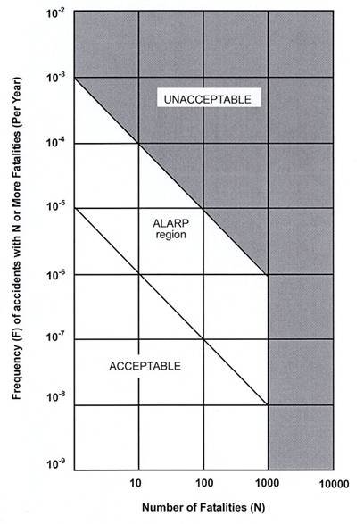
Societal risk expresses the risks to the whole population. The HKRG is
presented graphically in Figure
1. It is expressed in terms of lines plotting the
frequency (F) of N or more deaths in the population from incidents at the
installation. Two F-N risk lines are used in the HKRG that demark “acceptable”
or “unacceptable” societal risks. The intermediate region indicates the
acceptability of societal risk is borderline and should be reduced to a level which is “as low
as is reasonably practicable” (ALARP). It seeks to ensure that all practicable
and cost effective measures that can reduce risk will be considered.
Explosives Store (300kg
Capacity)
|
|
Figure 1 Hong Kong Government Risk Guidelines
10.10
The
objective of the QRA study is to assess the risk to life of the general public
from the hazards that arise
from the storage, use and transport of the explosives that are required to
facilitate the construction of the WIL project. The results of the QRA are
compared with the HKRG.
10.11
The detailed
requirements of the study are (see section 3.4.6 of
the EIA study brief):
·
To
identify all credible and applicable hazardous scenarios associated within the
boundaries of the construction site during the transport, storage and use of
explosives for blasting operations;
·
To
carry out a QRA to determine risks to the surrounding population in both
individual and societal terms;
·
To
compare the individual and societal risks with the Criteria for Evaluating
Hazard to Life stipulated in Annex 4 of the EIAO-TM;
·
To
identify and assess the practicable and cost effective risk reduction measures
as appropriate; and
The methodology of the hazard
assessment shall be agreed with the Director taking into account relevant previous
studies.
10.12
The elements of the QRA are shown schematically in Figure 2. It includes the following:-
·
Relevant data on the proposed storage magazine, the transport from the
magazine and the use of explosives at the blast face, as well as population and
vulnerable receptors, such as slopes, retaining walls etc., in the vicinity of
the tunnel construction and proposed transport routes were collected and
reviewed.
·
A structured study, involving a “what-if” analysis, was conducted to
identify all the hazards associated with the storage, transport and use of the
proposed blasting explosives. A review of literature and accident databases was
also undertaken. These formed the basis for identifying all the hazardous
scenarios for the QRA study.
·
The frequencies, or the likelihood, of the various outcomes that result
from the hazards associated with the storage and transport of blasting
explosives were taken from published references; such as the UK HSE, TNO, or
from previous EIA QRAs that have been accepted by the relevant authority. Where
necessary, these frequencies are modified to take account of project specific factors.
·
The frequencies of scenarios associated with the use of explosives at
the blast face were established using fault tree analysis, in conjunction with
a human factor assessment to evaluate human error probabilities.
·
For all identified hazards, the consequences of the event were modelled.
·
The consequence model employed by the QRA varied depending on the
location of any explosion, i.e. above or below ground, and upon the receiver,
i.e. slope, building or person.
·
The consequence and frequency data were subsequently combined using
ERM’s proprietary software Riskplot TM to produce the required risk estimates.
·
Finally, the results from the risk assessment were compared to the HKRG.
Recommendations have been made where required to ensure compliance with
relevant best practice, and to reduce the hazard by strengthening various
vulnerable receptors.
Figure 2 Schematic Diagram of QRA Process
Project Overview
10.13
WIL Construction is scheduled to commence in early 2009 for completion
in 2014. A significant length of the WIL will be excavated in rock. The amount
of rock to be extracted is approximately 480,000 m3. The rock excavation strategy as
well as the interfaces between the various contractors are shown in Figure 3.
10.14
Two types of explosives will be used for the construction of WIL by
Drill and Blast methods. These are:
·
Cartridged
Emulsion Explosives, which is classified as an explosive Class 1.1D under UN
Classification and as a Category 1 (Explosive and blasting agents) Dangerous
Goods under the Hong Kong Dangerous Goods Ordinance; and
·
Bulk
Emulsion Precursor, which is classified as an oxidising agent Class 5.1 under
the UN Classification system and as Category 7 (Strong supporter of combustion)
under the Hong Kong Dangerous Goods Ordinance. It is not classified as an
explosive until it is sensitised immediately prior to use.
10.15
Cartridged emulsion will be delivered from the Explosive Magazine to the
various construction sites by the appointed contractors using trucks licensed
by Mines Division. The bulk emulsion precursor will be transported to the blast
sites within the Adits/Tunnels by the appointed third party supplier. Bulk
emulsion will not be stored within the magazine.
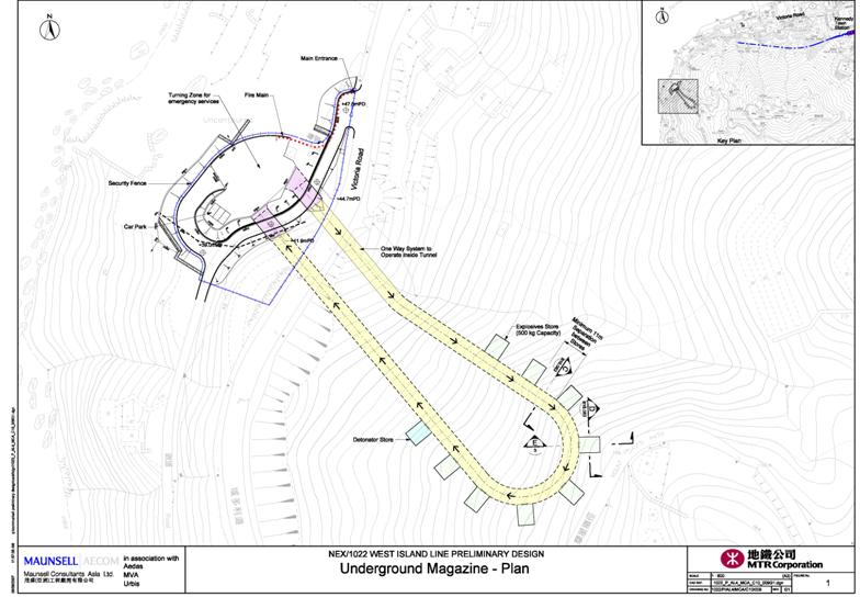
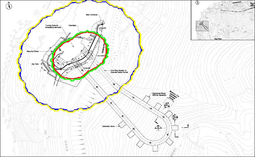
10.16
The location for the underground project magazine is an underground
store near a disused Government Facility Site with an entrance near Victoria Road (see Figure 4). The proposal is to use an existing flat platform of
land to access an underground store built into the mountainside beneath Mount Davis.
10.17
In much lesser explosive quantities, detonators, primers and detonating
cords will be used to initiate the blast at the working face depending on the
blast requirement. These are also classified as Class 1.1 explosives under the
UN classification system and Category 1 (Explosives and Blasting Agents) under
the Hong Kong Dangerous Goods Ordinance.
Detonators approved for use in Hong Kong
are of the Non-Electric Type, ie. chemically initiated.
10.18
For the purpose of this study, it is assumed that the construction
project will use cartridged emulsion explosives only. This represents the worst
case as the use of Bulk Emulsion Precursor will significantly reduce the amount
of cartridged emulsion (Cat 1.1D explosive) required to be stored and
transported.
Storage Magazine
Details
10.19
The proposed magazine is to be built into the mountainside beneath Mount Davis
and located near a disused Government Facility Site with an entrance near Victoria Road. The
design, construction and operation of the magazine, including the transport of
explosives and detonators to the point of usage, will be in accordance with the
Mines Division requirements.
10.20
The magazine will comprise an access tunnel 335m long, in an extended U layout, with explosive
storage chambers constructed off the side of the access tunnel. The access
tunnel portals will be located adjacent to one another and overlook the Sulphur
Channel. The explosive storage chambers will be located from the mid-point
along the tunnel, at the area with maximum depth below the ground surface.
10.21
The overall storage capacity of the magazine is 2400kg of blasting explosives.
The magazine is to comprise nine (9) chambers. Each chamber is designed to
store a maximum of 300 kg of
explosives. Eight chambers will store cartridged emulsion, detonating cords,
boosters, and primers. The ninth chamber will be used solely for the storage of
detonators.
10.22
The storage chamber for the detonators shall be sufficient to hold 9000
detonators, equivalent to two days supply. The detonators have a very low
explosive mass and contain less than 1 gramme of high explosives per detonator.
Therefore, the net explosive quantity from the total amount of detonators
stored is less than 9 kg.
10.23
The magazine design incorporates an automatic fire detection and alarm system
along the entire magazine tunnel length. Fire fighting measures such as fire
hydrant system are also provided in the magazine.
10.24
The magazine portals will have re-enforced concrete barriers or portal
barricades. These will be positioned in front of the entrance and exit adits of
the magazine, and designed in accordance with appropriate international
standards. The barricade walls are to be faced with a material designed to
retain any possible debris that may be propelled from the magazine adits.
10.25
The magazine will also have necessary security arrangements. These
include
·
2.5m high security fence topped with
razor wire;
·
Electric
flood lights evenly spaced along the security fence;
·
Close
Circuit Television (CCTV) camera mounted at 6m above the magazine ground level;
·
24hr
security patrols with at least two (2) armed guards during the day and three
(3) during the night;
·
Guard
dog; and
·
A
3 key system such that the authorised shotfirer, the contractor’s
representative, and the magazine manager have separate keys, with all three (3)
keys required for access to the chamber.
Transport Route Details
10.26
The overall intent is that Mines Division will deliver explosives daily
to a maximum of one construction site and the project magazine, from where
explosives will be transferred to the point of use by the contractors.
·
Two deliveries will be made each day to most of the delivery points. The
first delivery each day will be made in the early morning when roads will be
relatively quieter.
·
Loads will be limited to a maximum of 125kg per truck, which is the maximum load expected
for the project.
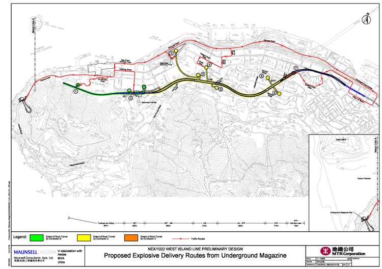
10.27
The Cartridged Emulsion Explosives will be delivered to the various
construction sites using the public roads as shown in Figure 5. The proposed site delivery points are the access shafts
at:
1.
Ex-police quarters, Kennedy
Town;
2.
Kennedy Town Swimming Pool (Smithfield Road);
3.
Site at Kennedy
Town Praya;
4.
Site at end of South Lane;
and
7.
Site at Sai Woo Lane.
10.28
According to the current programme of work, delivery of cartridged
emulsion explosives to points 1, 2, 3, 4 and 7 will be required from 2009 to
2011. Construction Phase I will require delivery of cartridged emulsion to
Points 1 to 4 and 7 while Construction Phase II will only require delivery of
cartridged emulsion to Points 3 and 4. There will be no overlap between the two
phases.
10.29
Other access points will not be used for delivery of explosives from the
magazine.
10.30
The maximum amount of anticipated daily deliveries of cartridged
emulsion by the contractors to points 1, 2, 3, 4 and 7 for Construction Phase I
is summarised in Table
1 below, while the maximum anticipated daily delivery to
points 3, 4 for Construction Phase II is summarised in Table 2 below.
10.31
The deliveries to point 7 will either be carried out in the morning or
in the afternoon. In addition to cartridged emulsion, detonating cords and cast
boosters, will be stored and transported. The explosives delivery quantities
are summarised in Table 1 and Table 2 for Construction Phase I and Phase II
respectively. Construction Phase I has the highest transport frequency per year
and hence been selected as the basis of the QRA.
|
Contractor
|
Delivery Point
|
Daily AM Delivery
(kg/day)
|
No of Trips AM
|
Daily PM Delivery
(kg/day)
|
No of Trips PM
|
Consumption (kg/day)
|
|
Contractor B
|
1 – Ex-police-quarters, Kennedy Town
|
80
|
1
|
0
|
0
|
80
|
|
2 – Kennedy
Town Swimming Pool
|
80
|
1
|
0
|
0
|
80
|
|
Contractor C
|
3 – Site at the Kennedy Town
Praya
|
125
|
2
|
125
|
2
|
500
|
|
4 – Site at the end of South Lane
|
80
|
1
|
80
|
1
|
160
|
|
Contractor D
|
7 – Site at the Sai Woo Lane
|
80*
|
1*
|
0*
|
0*
|
80
|
* Delivery may be carried out during PM instead of AM
Table 1 Explosives Delivery Quantities – WIL Construction Phase I
|
Contractor
|
Delivery Point
|
Daily AM Delivery
(kg/day)
|
No of Trips AM
|
Daily PM Delivery
(kg/day)
|
No of Trips PM
|
Consumption (kg/day)
|
|
Contractor C
|
3 – Site at the Kennedy Town
Praya
|
80
|
1
|
80
|
1
|
160
|
|
4 – Site at the
end of South Lane
|
80
|
1
|
80
|
1
|
160
|
Table 2 Explosives Delivery Quantities –
WIL Construction Phase II
10.32
The licensed explosives delivery vehicles will have the following safety
features:
·
Diesel powered
·
Battery and fuel isolation switches
·
Forward mounted exhaust with spark arrestor
·
Two fire extinguishers
·
Lockable wood lined steel magazine mounted on the vehicle tray
·
Fold down / up explosives warning signs and rotating flashing light
Use of Explosives Details
10.33
Explosives will be used for the initial construction of the storage
magazine as well as for the WIL alignment.
Adits / access tunnels will also be constructed by blasting.
10.34
The initial excavation of the magazine access tunnel will be by
mechanical methods. This will extend for 40 m until the tunnel has passed beneath Victoria Road.
Drill and blast excavation will then be adopted for a further 10 m for trial blasting, followed by full
face excavation if ground conditions are suitable.
10.35
The WIL alignment will be constructed in a similar
manner as the magazine adit/tunnel. The adit blasting will generally commence
at the bottom of the shafts, which are at typical depth of 20-40m but can be as deep as 80-90m near UNV Station. Blasting cover
protection will be provided to all shafts prior to blasting being carried out
in the adits.
10.36
The following safeguards will be implemented during
blasting.
10.37
Vibration Monitoring. It is a requirement to
monitor every blast in Hong Kong to record
blast induced ground vibrations. A dedicated Geotechnical Engineer is
responsible for ensuring that the controlling and other nominated sensitive
receivers for each blast are monitored to record the vibration levels in terms of Peak Particle
Velocity (mm/sec).
10.38
Trial Blasts. Trial blasts will be carried out for
the first series of blasts for the tunnels and adits and different areas or
sectors of the project if required. The trial blasts will be used to
demonstrate that the different types of blasting are safe, and the blasting
monitoring and control procedures are effective. The trial blasts are conducted
with cartridged emulsion explosives.
10.39
Advance Notice of Blasts. As part of the process of
issuing a License to Possess and a Permit to Use dangerous goods, Mines
Division will require that highly visible warning notices/signs be posted at
several locations to warn the public that blasting will take place. These
warning signs will be posted near the intended blasting location, even though
all blasts will be conducted underground. The Contractor is required to write
the blasting date and time on the notice.
10.40
Contractors are required by Law to have a comprehensive
Safety Management System and this is implemented and supervised by on-site
safety teams. Independent third party auditors make annual checks of
documentation and safety records.
10.41
Population
data used for the storage and transport risk assessment have been collected by
a combination of survey, the Code of Practice for Fire Safety (which defines
the maximum occupancy requirement for the design of commercial buildings),
Planning Department Zoning Plans and the census. Three types of population have
been considered:
·
Pedestrian population on footpaths and pavements next to delivery
routes;
·
Road population; and
·
Building population.
10.42
For the use of
explosive, all the features along the WIL alignment have been considered in a three
dimensional analysis. The features subject to the study include man made slopes
and retaining walls, existing man made features, natural terrain hillside and
boulders, existing buildings and structures, and utilities. The population data
was determined for the features that may be impacted by the hazards.
10.43
Details of
population adopted in this Hazard to Life assessment are provided in Appendix 10.
10.44
Hazard identification consisted of review of
explosive properties, review of scenarios in previous relevant studies, review of historical accidents and
discussions with blasting specialists. In addition, an expert panel review was
commissioned by ERM/MTRC to review the key assumptions and methodology for the
risk assessment for the storage, transport and use of explosives in the context
of the WIL Quantitative Risk Assessment. The review was held at ERM office in Hong Kong on 21-23 July 2008.
Type of Explosives
10.45
The blasting explosives configuration to be used for WIL will be either:-
·
A Detonator, containing less than a gram of high explosive such as PETN,
which is sufficient to detonate a Primer. The primer can be a single stick of
cartridged emulsion, or 12 grams of PETN or Pentolite (PETN/TNT
mixture). This in turn provides sufficient energy to set off the sensitised
bulk emulsion that is loaded into the blast hole.
·
Alternatively, a number of cartridged
emulsion sticks can be loaded into the blast hole and ignited by a single
detonator.
10.46
Both of the cartridged and bulk emulsions
contain mainly ammonium nitrate (single salt), water, hydrocarbon such as fuel
oil, and aluminium (only for the cartridged emulsion). Bulk emulsion is less
sensitive than the cartridged emulsion, as indicated by the requirement of an
explosive booster to initiate its detonation.
10.47
Cartridged Emulsion and Bulk Emulsion
Precursor will not explode due to friction and impact found in normal handling.
However, they can be detonated under heat and confinement or severe shock, such
as that provided by an explosive. In a fire, pools of molten ammonium nitrate
may be formed and if the molten mass becomes confined it may explode. In a fire
ammonium nitrate may melt and decompose with the release of toxic fumes (mainly
oxides of nitrogen).
Hazards of Explosives
10.48
Explosives present a hazard to both property and
people. This hazard manifests itself in the following five ways:
·
Blast and pressure wave;
·
flying fragments or missiles;
·
thermal radiation;
·
cratering; and
·
ground shock.
10.49
Blast and pressure waves can cause injury due
to sensitive human organs such as the ears and lungs. However, considerable
overpressures are required for fatalities to occur, and consequently people
need to be fairly close to the scene of the direct explosion effects to be
significant.
10.50
Other effects due blast or over-pressure are
associated with collapse of buildings and other structures/ objects or the
impact of debris and fragments from damaged building structure, and the vehicle
or container in which the explosives are held. Alternatively, injury may occur
when people are ‘swept’ away, or due to the violent movement of internal organs
within the body.
10.51
An explosion will involve the formation of a short
duration fireball, which is formed as the fuel content of the emulsion is
oxidised. However, although a fireball may be produced it will be of very short
duration. Generally it is considered that the thermal hazards from an
explosives detonation event are of less concern than the blast and fragment
hazards.
10.52
An explosion in an underground storage chamber may
produce external airblast from two sources; the exit of blast from existing
openings such as the magazine adits, and the rupture or breach of the chamber
cover by detonation. However, airblast hazards from a blast that ruptures the
earth cover are negligible relative to the ground shock and debris hazards.
10.53
The detonation of explosives liberates energy by a
rapid chemical reaction process, which produces and sustains a shock wave in
the surrounding rock. The degree of vibration of the rock particles decreases
with increasing distance from the blast. However, the vibration of the rock
particles can cause damage and structural failure to
buildings and other structures/ objects if it is sufficiently strong.
Review of Incidents
10.54
A review of reported safety incidents involving the
use of explosives (industrial applications) was carried out. Records were
retrieved mainly from the UK Health and Safety Executive (UK HSE)’s Explosives
Incidents Database Advisory Service (EIDAS), US Mine Safety and Health
Administration (MHSA) and Western Australia’s Department of Consumer and
Employment Protection (DOCEP). The records provided are also supplemented with
information obtained from various sources. Analysis of accident data are
provided in the Appendix 10.
Scenarios for QRA Study
10.55
Scenarios for the QRA study were identified based on the review of
incident records and previous similar QRA studies of explosives.
10.56
Scenarios considered for the transport of explosives are:
·
Accident involving explosives
delivered and transferred from magazine to delivery point 1
·
Accident involving explosives
delivered and transferred from magazine to delivery point 2
·
Accident involving explosives
delivered and transferred from magazine to delivery point 3 – Construction
Phase 1
·
Accident involving explosives
delivered and transferred from magazine to delivery point 3 – Construction
Phase 2
·
Accident involving explosives
delivered and transferred from magazine to delivery point 4
· Accident involving explosives delivered and transferred from magazine to
delivery point 7
10.57
Scenarios considered for the storage of
explosives are:
·
A fire leading to the detonation
of a full load of explosives within the magazine access tunnel whilst
transferring explosives to or from the appropriate storage chamber; and
·
A fire within any explosive
storage, or detonator, niche causing the detonation of the full quantity stored
within that particular niche.
10.58
Scenarios considered for the use of
explosives are:
·
Higher vibration generated by the
blast face due to human errors and other reasons such as manufacturing defects
causing deviation from the confirmed design;
·
Higher vibration and air
overpressure due to the detonation of a full load, 125kg, of explosives within the tunnel whilst
transferring explosives to the appropriate blast site.
10.59
The details of the frequency assessment are provided in
Appendix 10. The results are summarised below.
Frequency analysis for
Transport of Explosives
10.60
The basic event frequencies assumed for road accidents were based on that ‘The Risk
Assessment of the Transport of Explosives in Hong Kong QRA Report’ (ref. 4) due to its relevancy to WIL project, ie. transport
of explosives in Hong Kong.
|
Event
|
Event type
|
Value
|
|
Vehicle crash
|
Frequency
|
1.8 x 10⁻⁷ /km
|
|
Crash fire
|
Frequency
|
7.7 x 10⁻¹¹ /km
|
|
Non-crash fire
|
Frequency
|
1.4 x 10⁻⁹ /km
|
|
Explosives initiation in fire
|
Probability
|
0.1
|
|
Explosives initiation in impact
|
Probability
|
0.001
|
|
Explosives initiation due to unsafe Explosives
|
Frequency
|
3.28 x 10⁻¹² /km
|
Table 3 Explosives Initiation Fault Tree
Inputs
10.61
The frequency of explosives initiation during road transport is
thus estimated as 3.31 x 10⁻¹⁰/km, using a fault tree approach.
Frequency analysis for
Storage of Explosives
10.62
The overall initiating event frequency within the
storage magazine is based upon the UK HSE recommended value of 1 x 10⁻⁴
per storehouse year (see Section 6.1.1 of Appendix
10).
Frequency analysis for Use of Explosives
10.63
A failure mode analysis was carried out to
determine the potential failure modes associated with the use of explosives,
leading to higher vibration. The scenario of 2 or more maximum instant charges
(MIC) detonated at the same time was identified for the risk assessment. Fault
tree analysis was conducted, in conjunction with human factor assessment to
determine the occurrence frequency of 2 or more MIC detonated at the same time.
10.64
Table 4 summarises the overall frequency for
failure scenarios leading to higher vibration for the whole WIL project. The
blast linear length refers to the total pull length by the drill and blast
operation. For the WIL alignment, the blast linear length includes the two running
tunnels, two station blocks and associated adits and is estimated as about 9.3 km. For the Magazine Store, the blast
linear length covers the access tunnel and the 9 niches, and is estimated about
0.4 km.
|
Sections
|
Blast Linear
Length
|
Occurrence Frequency
for multiple MIC detonated at the same time per Section (Occurrence for the
whole project)
|
|
2MIC
|
3MIC
|
4MIC
|
5MIC
|
6MIC
|
|
WIL Alignment
|
9.3 km
|
4.09E-01
|
1.16E-03
|
6.86E-06
|
6.86E-06
|
6.86E-06
|
|
WIL Magazine Store
|
0.4 km
|
1.05E-02
|
2.73E-05
|
1.89E-07
|
1.89E-07
|
1.89E-07
|
|
Overall for WIL
project
|
9.7 km
|
4.19E-01
|
1.19E-03
|
7.05E-06
|
7.05E-06
|
7.05E-06
|
Table 4
Overall Frequency for Failure Scenarios leading to Higher Vibration for the
Whole Project Phase
10.65
This section gives a brief summary of the approach
adopted to model the consequences of an explosion within the magazine. Details
are given in Appendix 10.
10.66
The probability of fatality due to blast
over-pressure, have been estimated using the method detailed by the UK HSE Explosives
Storage and Transport Committee (ESTC) (ref. 5). The probability of fatality due to the possible damage
/ failure of a building, or slope, due to ground shock has also been modelled
using methods detailed with the Hong Kong CEDD Geo Reports (ref. 7-8). The fatality contours are calculated at 1%, 50% and 90% fatality.
10.67
Ground
shock or vibration levels at a given receptor will depend on the
distance between the receptor and the blasting point. The estimation of ground
vibration levels has used the method published in the Hong Kong CEDD Geo Guide
4 Cavern Engineering (ref. 6).
Consequence Distances
10.68
The
consequence distances for explosion events using the ESTC model are summarized
in Table 5. In this table, the ‘indoor’ refers to the
population located inside buildings, and the ‘outdoor’ refers to the population
located outside buildings ie in open area. A sample calculation of ground vibration level
is shown in Table 6.
|
Scenario
|
Description
|
TNT eqv. (kg)
|
Indoor
|
Outdoor
|
|
Harm Prob.
|
Impact distance
(m)
|
Harm Prob.
|
Impact
distance (m)
|
|
R01
|
Initiation of explosives during transport of
explosives from magazine to delivery point 01 via route 01
|
77
|
90%
|
13
|
90%
|
11
|
|
50%
|
15
|
50%
|
11
|
|
1%
|
36
|
1%
|
14
|
|
R02
|
Initiation of explosives during transport of explosives
from magazine to delivery point 02 via route 02
|
77
|
90%
|
13
|
90%
|
11
|
|
50%
|
15
|
50%
|
11
|
|
1%
|
36
|
1%
|
14
|
|
R03
|
Initiation of explosives during transport of
explosives from magazine to delivery point 03 via route 03
|
120
|
90%
|
15
|
90%
|
12
|
|
50%
|
18
|
50%
|
13
|
|
1%
|
42
|
1%
|
16
|
|
R04
|
Initiation of explosives during transport of
explosives from magazine to delivery point 04 via route 04
|
77
|
90%
|
13
|
90%
|
11
|
|
50%
|
15
|
50%
|
11
|
|
1%
|
36
|
1%
|
14
|
|
R07
|
Initiation of
explosives during transport of explosives from magazine to delivery point 07
via route 07
|
77
|
90%
|
13
|
90%
|
11
|
|
50%
|
15
|
50%
|
11
|
|
1%
|
36
|
1%
|
14
|
|
S01
|
Initiation of
explosives at delivery point 01
|
77
|
90%
|
13
|
90%
|
11
|
|
50%
|
15
|
50%
|
11
|
|
1%
|
36
|
1%
|
14
|
|
S02
|
Initiation of
explosives at delivery point 02
|
77
|
90%
|
13
|
90%
|
11
|
|
50%
|
15
|
50%
|
11
|
|
1%
|
36
|
1%
|
14
|
|
S03
|
Initiation of
explosives at delivery point 03
|
120
|
90%
|
15
|
90%
|
12
|
|
50%
|
18
|
50%
|
13
|
|
1%
|
42
|
1%
|
16
|
|
S04
|
Initiation of
explosives at delivery point 04
|
77
|
90%
|
13
|
90%
|
11
|
|
50%
|
15
|
50%
|
11
|
|
1%
|
36
|
1%
|
14
|
|
S07
|
Initiation of explosives at delivery point 07
|
77
|
90%
|
13
|
90%
|
11
|
|
50%
|
15
|
50%
|
11
|
|
1%
|
36
|
1%
|
14
|
|
M1
|
Explosion within magazine chamber 1 – 8
(Cartridge Explosives)
|
300
|
90%
|
17
|
90%
|
21
|
|
50%
|
17
|
50%
|
24
|
|
1%
|
22
|
1%
|
63
|
|
M2
|
Explosion within magazine chamber 9 (Detonators)
|
9
|
90%
|
5
|
90%
|
7
|
|
50%
|
5
|
50%
|
8
|
|
1%
|
7
|
1%
|
20
|
Table 5 Consequence Distances for Explosive Initiation using ESTC Model
|
Feature
|
Min
Distance from closest chainage (m)
|
Closest
Blast Chainage
|
Explosive
charge used (kg)
|
PPV
expected (mm/s) - 2 charges per delay
|
PPV
expected (mm/s) - 3 charges per delay
|
PPV
expected (mm/s) - 4 charges per delay
|
PPV
expected (mm/s) - 5 charges per delay
|
PPV
expected (mm/s) - 6 charges per delay
|
|
Bld1
|
33
|
SYPSHW_EB_100010
|
4.1
|
61
|
78
|
93
|
106
|
119
|
|
Bld2
|
29
|
SYPSHW_WB_100013
|
3.6
|
66
|
85
|
101
|
116
|
129
|
Table 6 Sample Calculation of PPV Level for each Feature at 2 or more MIC
detonated at the same time
Individual Risk Results
10.69
The individual risk (IR) contour associated with WIL
project are shown in Figure
6, Figure
7, Figure 8 and Figure 9. In these figures, the ‘indoor’ refers to the
population located inside buildings, and the ‘outdoor’ refers to the population
located outside buildings ie in open area.
10.70
The IR contours for ‘indoor’ and ‘outdoor’ have
been presented separately as the fatality probability is different for indoor
and outdoor population. The current version of the Riskplot model enables to
present indoor and outdoor fatality separately. This approach is more rigorous
than the equivalent fatality model since the effect distances for indoor and
outdoor fatality could be quite different.
For the
delivery routes, it is observed that no section of routes has an IR exceeding 5
x 10-8 per year. The highest risk contour at 1 x 10⁻⁷ (in
red colour of Figure 6 and Figure 7) represents the scenario of detonation of a full load
of explosives within the tunnel whilst transferring explosives to the blast
site, as part of use. For rock excavation using explosives, features at risk were
identified and the maximum risk of fatality to any individual is estimated as
4.4 x 10⁻¹⁰ per year. This is much lower than the Individual Risk
Criteria of 1 x 10⁻⁵ per year.
10.71
The IR contour for magazine is a 2 dimensional representation and hence
does not account for the relative elevation of the magazine portal with respect
to the receptor at risk. Also considering the most exposed individual in the
vicinity of the magazine, the individual risk is below 1 x 10⁻⁵ per
year and hence is acceptable.
Figure 6 IR of Delivery Route (Indoor)
Figure 7 IR of Delivery Route (Outdoor)
Figure 8 IR of Proposed Magazine (Indoor)
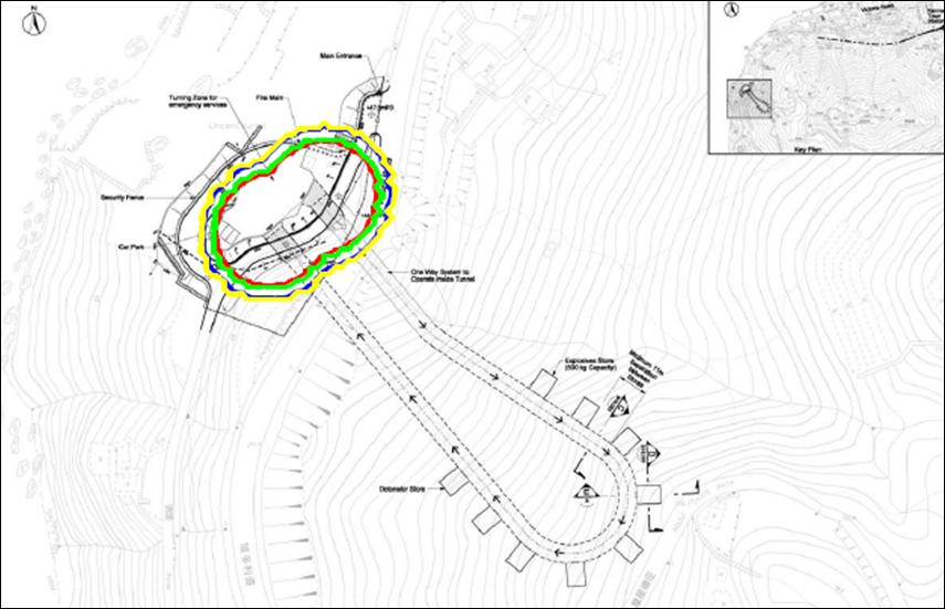
Figure 9 IR of Proposed Magazine (Outdoor)
Societal Risk Results
10.72
The societal risk results for the transport,
storage and use of explosives have been combined to produce the overall
societal risk results (Figure 10).
10.73
During phase 1 of the construction, there is an option to deliver
explosives to point 7 at AM or PM time, whereas deliveries to other points will
be as per the timing indicated (see Table
1). The FN curve for transport has been presented for
delivery to point 7 pm case which is the worst amongst the am and pm case for
pt 7 and it includes delivery to other points as well. The FN curve for use of
explosives covers construction of the WIL alignment and the magazine store.
10.74
The risks for all cases are within the Acceptable
Region as per EIAO.
10.75
The potential Loss of Life (PLL), or equivalent
fatalities per year, is given in Table 7. The total PLL for the whole WIL project is 3.44 x 10⁻⁵
per year, or equivalent to, one fatality every 30,000 years.
Figure 10 FN Curves
|
Case
|
PLL (per year)
|
Percentage Contribution (%)
|
|
Transport of
Explosives
|
|
|
Delivery of
explosives from magazine to delivery point 1
|
1.26E-06
|
3.66%
|
|
Delivery of
explosives from magazine to delivery point 2
|
1.68E-06
|
4.89%
|
|
Delivery of
explosives from magazine to delivery point 3
|
9.39E-06
|
27.29%
|
|
Delivery of
explosives from magazine to delivery point 4
|
6.04E-06
|
17.57%
|
|
Delivery of
explosives from magazine to delivery point 7
|
8.80E-06
|
25.57%
|
|
Use of
Explosives
|
|
|
Construction of
magazine
|
1.13E-08
|
0.03%
|
|
Construction of
WIL alignment
|
1.26E-06
|
3.67%
|
|
Detonation of
explosives within the tunnel whilst transferring explosives to the blast site
at delivery point 1
|
8.99E-08
|
0.26%
|
|
Detonation of
explosives within the tunnel whilst transferring explosives to the blast site
at delivery point 2
|
1.74E-07
|
0.51%
|
|
Detonation of
explosives within the tunnel whilst transferring explosives to the blast site
at delivery point 3
|
1.82E-06
|
5.29%
|
|
Detonation of
explosives within the tunnel whilst transferring explosives to the blast site
at delivery point 4
|
3.35E-06
|
9.73%
|
|
Detonation of
explosives within the tunnel whilst transferring explosives to the blast site
at delivery point 7
|
4.28E-07
|
1.25%
|
|
Storage of
Explosives
|
|
|
Proposed
magazine, including transport within the adits
|
9.04E-08
|
0.26%
|
|
Total
|
3.44E-05
|
100.00%
|
Table 7 Potential Loss of Life
References
1. MTR, West Island Line,
Consultancy Agreement C703, SYP and UNV Stations, and SHW to KET Tunnel, Blast
Assessment Report, Volume 1-8, June 2008
2. MTR, West Island Line,
Consultancy Agreement C704, KET Station and Overrun Tunnel, Modifications to
SHW Station, Blast Assessment Report, Volume 1-3, July 2008
3. MTR, West Island Line,
Consultancy Agreement C703, SYP and UNV Stations, and SHW to KET Tunnel,
Explosives Magazine at Victoria
Road Controlling Blast Report, June 2008
4. DNV The
Risk Assessment of the Transport of Explosives in Hong Kong, EPD
1997.
5. HSC,
Selection and Use of Explosion Effects and Consequence Models for Explosives,
Advisory Committee on Dangerous Substances, 2000
6. CEDD, Geoguide 4 - Guide to Cavern Engineering, Chapter 5,
pp77-78
7. CEDD, GEO Report 15, Assessment of Stability of
Slopes Subjected to Blasting Vibration, by H.N. Wong & P.L.R. Pang, 1992
8. CEDD, GEO Report 81 Slope Failures along BRIL Roads :
Quantitative Risk Assessment and Ranking, by ERM-Hong Kong, Ltd, 1999
9.
Lees, Frank P, Loss Prevention in the Process
Industries, second edition, 1996.
10.
Lees, Frank P, The Assessment of Major Hazards: A model for fatal injury
from burns, trans IChemE Vol 72, Part B, 1994.
11.
Merrifield, R. and Moreton, P A. An Examination of the Major Accident
Record for Explosives Manufacturing and Storage in the UK. Journal of Hazardous Materials
A:63 (1998) 107-118. 1998.
12.
Guidelines for Quantitative Risk Assessment. CPR18E. “Purple Book”.
Committee for Prevention of Disasters (The Netherlands). 1999.
13. Advisory
Committee on Dangerous Substances (ACDS), Major Hazard Aspects of the Transport
of Dangerous substances, HSC 1991.